In the end, our bridge came out on top in efficiency, though it didn't quite hold as much weight. Using the equation mass supported over mass of bridge times 100, we were able to determine that our bridge's efficiency was 7278% while the other team's efficiency was only 6185%. While these are both rather strong numbers, the main reason that ours came out on top was because one one factor: the mass of the bridge. While our bridge was only 35.8 g, our opponents bridge was 48.7 g. Of course, if one were to predict which bridge should hold the most one would think it would be the heavier one, but when it comes to efficiency, in this case it didn't equal out. Our bridge held only 2620.9 g to our opponent's 2970.9 g, but the difference there is only slight in comparison to the difference between the two masses of the bridges. The leading question now however is, why did our opponent's bridge not come out on top despite what seems to be a superior design (pictured below)
To be concise, the reason is because of the sideways truss that our bridge utilized. Our opponent's bridge, though more sturdy throughout the process of adding weight, eventually began to twist at the top because it only had a slight support against side to side motion. On the other hand, though our bridge wasn't quite as sturdy in regards to the downward force exerted on it, it was very good at withstanding any form of twisting, therefore it was able to hold its shape.
Conclusions
To be perfectly honest, both of our teams made large errors in our bridge design that cost us valuable strength, but on the other hand though, both of us made very good choices in regards to what we did, so what can we do to improve our bridge designs?
Franky, the best way would have been to combine the ideas that both of our bridges worked on separately. Our opponent's bridge focused more on the downward forces that were going to be exerted on the bridge, but neglected to notice the sideways motions that would inevitably also occur when weight was added. Then, on the other side of the spectrum, our bridge instead focused more on the forces of torque instead of weight, and as a result was unable to hold as much downward force as our opponent's. In essence, if our opponents had utilized a design that focused a bit more on sideways motion, they likely would have completely outstripped our bridge, but the same could have been true for our bridge had we provided more support against downward motion. All in all, I feel that it taught both of our groups a lesson: don't ignore one force in favor of excessively counteracting the another.
Our construction process was very interesting indeed, as we repeatedly tried different ideas only to meet with many issues along the way. Our first thought was that we were going to create an arch bridge similar to that of the simple roman arch, but we encountered one major problem with that design: the fact that we couldn't actually get it to stay between the tables without falling through; it would have been liable to slip off with only the slightest weight added to it. With that in mind, and after 2 days of wasted planning, we decided that we would instead go with a more simple idea, a bridge with a strong deck and an arch that extended across the top instead of underneath, but this too ran into issues, not necessarily in design, but because of cost practices. When we originally built the deck, it was calculated out to be approximately $1300, which would have left us about $1200 to work on the arch, but once the deck was built we recalculated the cost and found out that we were quite literally only $36 under the maximum budget, making it impossible to build any sort of arch. As a result, instead of the arch, we decided that we would take the extra length that we had off of the end of the bridge and turn it into a sort of triangular truss in the very middle of the bridge, hoping to strengthen the spot where the two lengthwise skewers met but didn't connect. This strategy actually worked out extremely well for us, and saved us a lot of time in designing the arch, therefore it actually became somewhat of a blessing that we miscalculated in the first place, though perhaps with the arch our bridge may have stood up to more weight. In order to test that theory, we would just have to rebuild it with the arch and see which turned out to be better. In the end, the bridge came out to look like the picture above.
The Materials
In an effort to get the most support possible for our bridge, we used the bamboo skewers as the base of the deck. We figured that, if all else failed, the skewers would be flexible enough to hold together the rest of the structure even under extreme weight. We used 6 skewers to accomplish this, two from end to end to cover the length requirement and three across, though separated by a few fractional centimeters, in order to reach the width requirement. We then used toothpicks to form what I'm going to dub a sideways truss, both on the underside and on top of the three skewers. It was this sideways truss that helped to void the force of torque that acted on the bridge, because the force was distribute across the triangular formations. Finally, we used a truss made out of skewers and toothpicks on the bottom of the bridge in the middle in order to stabilize the point at which the skewers of the deck met. All in all, our design process focused more on the side to side, twisting motion of the force rather than the up and down forces of weight, which in the end is what gave our bridge the edge.
The next step in figuring out how to build our bridge was looking at the different forces that act on a bridge at various times and places on the structure. Ironically, many of the forces are rather simple ones that most everybody knows, it's just that they're specifically taken advantage of in the construction of a bridge.
Compression & Tension
Compression is the force that pushes two objects together. It can easily and simply be demonstrated by pressing the palms of your hands together. The harder one pushes, the more compression forces there are between the two hands. On the other hand (pun fully intended), tension is a force that is opposite to compression. Instead of the force that pushes two objects together, it is the force seen when an object is stretched in opposite directions. A very simple example that relates to bridges can be seen above. When an object is placed on top of a bridge, the weight it exerts downwards caused compression on the top of the deck, while causing tension on the bottom of the deck. When building a bridge, utilizing both of these forces becomes key in making sure that a bridge doesn't collapse as soon as weight is put on it.
Weight & Equilibrium
Weight is yet another concept that is extremely basic, yet is important to the building of a bridge. Weight is a force dependent upon Newton's Law of Universal Gravitation, as well as partially being related to Newton's Third Law, which states that every action has an opposite and equal reaction. Essentially, gravity is responsible for giving objects weight, which is shown by the equation for weight, w=mg where w is weight, m is mass, and g is the acceleration due to gravity (9.80 m/s^2 on Earth). This equation was derived from Newton's Second Law, which states that Force = Mass x Acceleration. The effect of weight on bridges is rather self-explanatory; the more weight that's on a bridge, the more force that is needed to counteract that weight. Though there are many different forces that act on an object to achieve equilibrium, we can get a general sense of equilibrium through weight. For instance, if a man is sitting in a chair, the system is in equilibrium. If the man weights approximately 50 N, then according to Newton's Third Law, the chair is pushing back with a normal force of 50 N as a result. The system extends even further into successive layers, as the ground that the chair is sitting on is pressing up on the chair with a force of 50 N, and the building is pressing up on the floor with a force of 50 N, and so on. According to Newton's First Law, which states that an object at rest will stay at rest unless acted on by an unbalanced force, the chair will stay at rest unless someone were to, say, push the chair from behind.
Torque
Torque is a force that provides a twisting motion to an object. That being said, it's important to prevent such a twisting on a bridge because it can lead to the bridge collapsing from the forces that exerted. To look at torque from an analytical perspective, it can be defined by the equation T=FL, where F is the force exerted and L is the lever arm. The lever arm can further be broken down into the equation L=rsin(theta), where r is the radius and theta is the degree measure formed by the line of action and the object being pushed. Torque became a major part of our bridge design, as you'll be able to see in the next post.
Vector Addition
When all is said and done, vector addition is the end all be all for determining the force and direction of any combined force. Basically, by using the magnitude and direction of two forces pushing on the same object, one can determine the resulting magnitude and force. Not only that, the resultant can be determined either graphically or algebraically. It's hard to put it into words exactly, but the graphical method is done by using the two forces to form a parallelogram, and using the diagonal of that parallelogram as the resultant vector. That kind of addition can be experimented with here. The alternate method, through algebra, is generally more common because of its accuracy compared to the graphical method. Again, it's a bit hard to explain, in words, but basically one must multiply the magnitude by the cosine of the degree measure for the horizontal factor of both, and then multiply the magnitude by the sine of the degree measure for the vertical factor. You then must add up the vertical and horizontal quantities, square the results, and take the square root of the squared results added together. This will give you the magnitude. The second part is finding the direction, in which case you use the inverse tangent of the vertical quantity over the horizontal quantity. In the case of the resultant being in the 2nd or 3rd quadrant, you then have to add 180 degrees, or if it is in the 4th quadrant, you have to add 360 degrees.
The first step in determining what to use for our bridge was a rather easy experiment involving Hooke's Law. Hooke's law is defined as F=-kx, where F stands for force, k is the spring constant, and x is displacement of the spring. This illustration demonstrates the law most accurately:
Basically, Hooke's Law is used to determine how much force it will take to make something stretch a certain distance from it's original point on an imagined Cartesian Plane. With this in mind, we used a force measurement tool to see just how strong each of the materials was. We did this by extending them across a gap and pulling down on them with an apparatus that measures how many newtons of force it takes to actually snap the material in half, or otherwise break it to the point at which it is unusable. As a result, we were able to determine that it took 21 N of force to break a bamboo skewer, and 3 N of force to break a coffee stirrer. Though we were unable to get the data for the toothpicks because we ran out of time in class, we can conjecture that they would be somewhat stronger than the coffee stirrers but nowhere near as strong as the bamboo skewers, mostly because the bamboo skewers had a large elasticity constant, meaning they were able to stretch far more without breaking. On the other hand, in casual observation one can tell that a toothpick does not flex even remotely as much as a skewer can, and therefore it would break far more easily.
To make a long story short, bamboo skewers were by far the best material to use in regards to strength, while the other two materials trailed far behind and had similar strength and elasticity.
This project began with a rather simple, to the point, essential question: How does one design the most efficient bridge by assessing materials and ensuring the support of a weight load? In essence, the challenge was to build a bridge that could support the most weight with the given materials, which were coffee stirrers, bamboo skewers, and wooden toothpicks.
With these materials in mind for the project, we also had to know that each of them had a certain cost that was attributed to them based on their cost in a store. As such, bamboo skewers were the most expensive and we calculated that their contest value would be $97 a piece. Then, coffee stirrers were the second most expensive coming in at $55 a piece, and lastly toothpicks cost $18 a piece.
With all this prior knowledge out of the way, we were able to determine the rules for our bridge building project, which were as follows
The bridge's cost could not exceed $2500 in materials
There could be no lamination (a successive build up of five or more consecutive layers (i.e. we couldn't make our bridge look like the above package of skewers).
The bridge had to be between 40 cm and 50 cm long with a width between 3 cm and 10 cm
These being the only real rules for the bridge, we set off on our bridge building journey.
From the very beginnings of time, bridges have been essential in spanning not only rivers, but great distances that humans cannot simply leap across. Some of the first bridges were hewn out of natural stone formations, but as humanity's exploits continued to expand, so did their ability to build bridges. Some of the first "artificial" bridges were built out of stone in the form of arches by the Roman Empire, as a way to transport not only goods but troops throughout their vast domains.
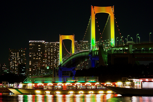
As time progressed, bridges came to span even more vast distances and become ever more complex. Instead of building an arch, which simply utilized compression for it's support (a force that we'll talk about later) people began to take advantage of tension, a force that is opposite to compression. As a result, suddenly bridges were not only built downwards, but also upwards. Perhaps one of the most stunning examples of the use of tension in bridge design is the Rainbow Bridge in Tokyo.
The resulting forces can be seen on the diagram to the left. The blue lines represent the forces of tension acting on certain parts of the bridge, while the red arrows signal where the forces of compression are acting.
Though there is far more history to bridges than what was outlined here, this serves as a concise look at how bridge building has changed from the past to the present.